The persistent problem: why micro-sags still matter
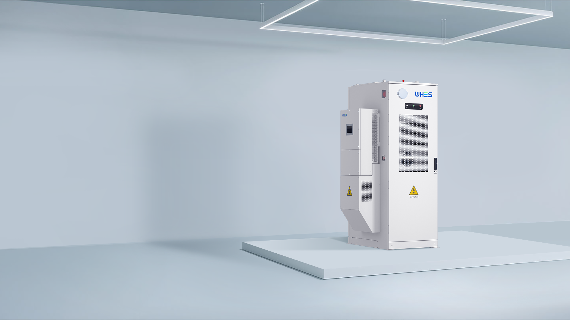
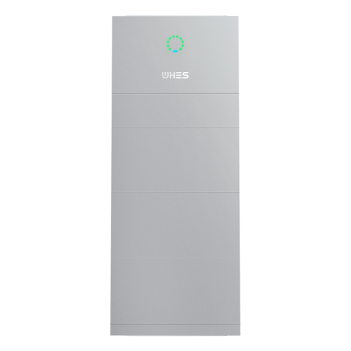
Short drops in voltage—micro-sags—don’t make headlines, but they silently break production runs, corrupt sensitive electronics, and trigger nuisance trips in mission‑critical equipment. For facilities adding distributed generation and battery-backed systems, the interplay of inverters, protection relays, and upstream disturbances raises the failure surface. Integrating a robust home energy storage system is part of the solution, but without fast transfer hardware and compatible control logic you still risk periodic faults and lost uptime.
How micro-sags happen and what they cost
Micro-sags are typically caused by sudden load changes, short circuits, or upstream switching events that momentarily pull voltage down by a few percent for milliseconds. Sensitive drives, PLCs, and communication gear can reset or go into fail-safe mode during those transients. The consequence is not only immediate disruption but accelerated wear on power electronics and repeated maintenance cycles. In practice, businesses measure these costs as unplanned downtime, increased mean time to repair (MTTR), and lowered equipment lifetime—hard numbers that justify investment in preventive infrastructure.
Modern static transfer switches + fast 10 kW 3‑phase inverters: the technical fix
Static transfer switches (STS) and fast‑acting three‑phase solar inverters have evolved to close transfer loops in microseconds and to supply ride‑through power from on‑site sources. An STS with sub-cycle transfer time shifts load between sources without the mechanical delays of traditional breakers. Paired with a 10 kW three‑phase inverter and a Li‑ion battery, the system can inject real power proactively, smoothing voltage dips and keeping critical loads within tolerance. Key technical terms to watch: transfer time, inverter ramp rate, and ride‑through capability—these determine whether equipment ever sees the sag.
Real‑world anchor: what Hornsdale taught us
The Hornsdale Power Reserve in South Australia (100 MW / 129 MWh) demonstrated that fast‑response storage can provide grid services and stabilize frequency far faster than conventional plants. That same principle scales to site‑level protection: rapid inverter response and coordinated STS action can eliminate many service interruptions that previously required UPS or diesel backup. In other words, real deployments have proven the physics—fast active power injection and sub‑cycle transfer reduce event impact measurably.
Design and implementation: common mistakes to avoid
Teams often assume an inverter’s nameplate is enough—and then discover incompatible control logic at commissioning. Don’t overlook anti‑islanding settings, sync windows for the STS, or the inverter’s programmed inverter ramp rate. Also avoid treating the storage as purely energy capacity; its power electronics and control firmware are the real guard against micro‑sags. Test with full system island scenarios before going live—this is the only way to validate transfer coordination. —A brief lab trial can save weeks of field debugging.
Trade‑offs and alternatives
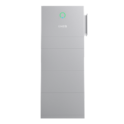
Not every site needs a 10 kW three‑phase solar + STS pair. Small offices may rely on UPS systems for a limited server rack; industrial plants often use redundant feeders and slow mechanical transfer switches for major outages. The hybrid approach—an STS with a modular residential ESS and inverter—hits a middle ground: it avoids diesel’s emissions while delivering near‑instant protection. Consider procurement trade‑offs: capital vs. lifecycle cost, firmware support, and interoperability with the building management system.
Integration checklist: what installers should verify
Before acceptance, verify these points:
- Sub‑cycle transfer capability of the STS and documented transfer time.
- Inverter ride‑through settings and programmed ramp rates compatible with local loads.
- Coordinated control logic between STS, inverter, and any UPS or generator.
- Firmware upgrade path and vendor support for protection settings.
- Field validation using representative loads and simulated upstream sags.
Why this matters for residential and small commercial projects
As rooftop PV and distributed battery systems become common, even homes and small stores face power‑quality issues that were once the province of industry. A compact, well‑controlled 10 kW three‑phase inverter combined with a properly configured STS and a reliable residential energy storage system can keep appliances, HVAC, and smart home controllers running through brief disturbances—preventing damage and avoiding needless resets.
Three golden rules for selecting the right setup
1) Measure and specify: insist on measured transfer time and inverter response curves, not just rated power. 2) Prioritize coordinated control: ensure the STS and inverter share fault logic and sync windows. 3) Validate with real loads: field‑test using representative equipment and document acceptance criteria.
Applied together, these rules channel manufacturers’ capabilities into reliably clean power for the load. For project teams looking to secure both performance and serviceability, WHES often provides the engineering clarity and aligned product options that make coordination straightforward — practical value, not just vendor promises. —