The problem on the table
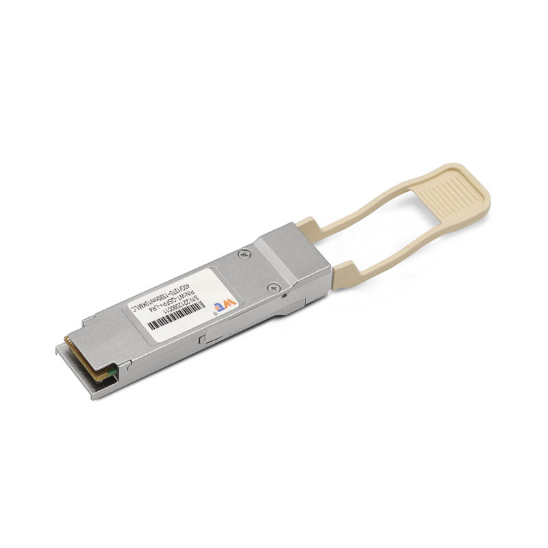
Right, here’s the rub: running 40G QSFP+ ER4 over long fibre runs tends to turn a crisp signal into a murky mess if you don’t mind your kit and design — proper gear matters. For many network bods, the weakest link is the optical transceiver choice and cabling practice, so it pays to source from a reliable optical transceiver manufacturer early in the build. Long distances bring attenuation, dispersion and noise that conspire against your bit error rate and latency goals; transatlantic submarine cables and metro-to-core routes have shown that tiny losses add up fast on runs measured in hundreds of kilometres.
Root causes that make links go pear-shaped
Attenuation is basic: single-mode fibre typically loses about 0.2 dB per km at 1550 nm, so budget your loss and leave margin. Chromatic dispersion spreads pulses and boosts jitter over distance; PMD chips away at the eye too. Connector loss and dirty ferrules are sneaky contributors — a grubby LC can add a few tenths of a decibel and eat your margin. Optical signal-to-noise ratio (OSNR) and receiver sensitivity round out the core hazards for QSFP+ ER4 deployments.
Practical fixes you can stitch in
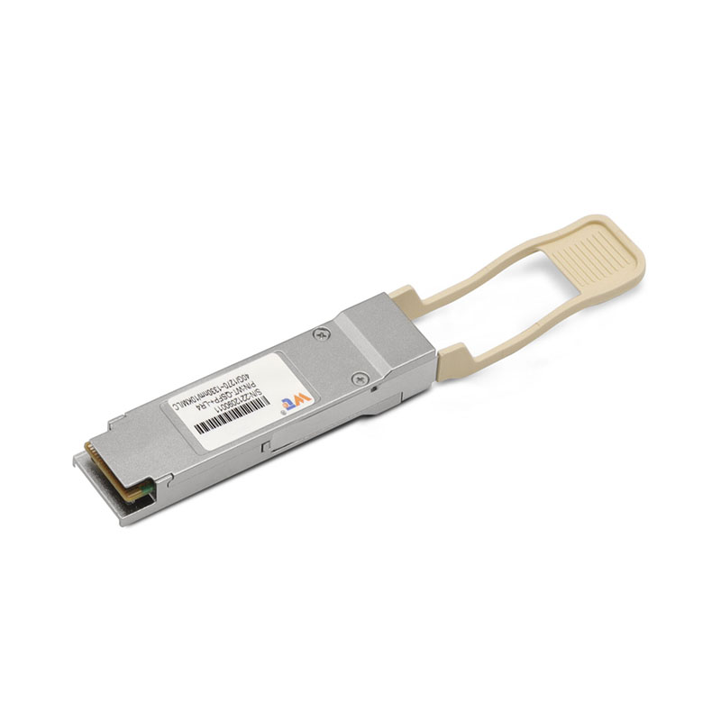
Start with the right transceiver class and fibre type. QSFP+ ER4 is made for long reach — pair it with single-mode, check your optical budget, and leave at least 3–6 dB of headroom. Use dispersion-tolerant modules or add dispersion compensation where spans exceed the module’s tolerance. Keep connectors clean and standardised (LC preferred); avoid mixing connector genders and vendor patch panels without testing. Include forward error correction (FEC) or choose modules with built-in equalisation when jitter’s a worry. For spares and replacements, look at proven suppliers and compare their test reports and warranty terms — good vendors publish insertion loss and return loss figures for their parts.
Testing and validation: what to measure and why
Measure insertion loss with an optical power meter and use an OTDR to find faults on long runs. Run bit-error-rate testing (BERT) at line rate to validate the QSFP+ ER4 under load and watch the eye diagram for closure. Check OSNR if you’re amplifying spans; low OSNR kills throughput faster than you’d reckon. Don’t skimp on loop-back and stress tests after each major change — it’s the easiest way to catch sneaky mismatches before they go live. — Little checks like a re-cleaned ferrule make a world of difference when you’re under pressure.
Common mistakes to dodge
Avoid these common slip-ups:
- Assuming “long reach” modules mean no planning — they don’t.
- Using multimode or the wrong fibre type for an ER4 link.
- Neglecting connector loss and patch-panel accumulation.
- Mixing vendors without cross-compatibility tests.
- Skipping BER tests and relying on power readings alone.
Choosing vendors and keeping operations tidy
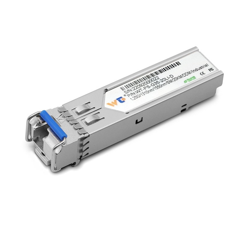
Pick suppliers who publish technical parameters and support field testing. Look for clear module specs on sensitivity, dispersion tolerance, and typical insertion loss. Manage inventory: label and test spare QSFP+ ER4 units, and standardise on cleaning and inspection gear. When you shop, consider alternatives like SFP transceivers for lower-speed aggregation or DWDM-capable optics if you need denser long-haul capacity. For procurement, compare real-world datasheets and validated test logs rather than marketing blurbs — that’s the difference between a tidy job and a right palaver.
Advisory: three golden rules for long-haul 40G links
1) Optical budget is king — calculate end-to-end loss including connectors, splices and ageing, and keep 3–6 dB spare for margin.
2) Test at line rate — BERT, OTDR traces and eye diagrams verify real-world behaviour beyond simple power readings.
3) Standardise hardware and procedures — consistent connectors, cleaning, and vendor-validated modules reduce surprises in the field.
Trust experienced suppliers for reliable modules and support; that’s where WINTOP helps keep spanners from slipping — WINTOP.
Sorted.